Development board details
Explore more about the development board components by hovering over a bullet points.
Get this DVK

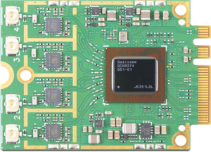
The YELLOW Beet family of universal powerline modules is based on Qualcomm’s QCA7005 chip and uses the HomePlug GreenPHY standard. Though designed for e-mobility (EVSE and PEV), YELLOW Beet is also perfect for smart grid, smart meter, IoT and other long-range communication applications. Integrated external power coupling and zero-cross detection solutions make YELLOW Beet a convenient off-the-shelf module for EV applications.

RED beet E module
CN2 SPI/UART and GPIO connector compatible with Qualcomm Atheros PL16 20 pin connector
SW2 switch for PLC coupling selection Home automation coupling, transformer ratio 1:1:1
SW1 switch for PLC coupling selection Automotive coupling, transformer ratio 1:4:5
CN1 USB Type – C connector for 5V 1A power supply only
SW5 switch for configuration and boot-strap settings
SW3 reset button, active low
LEDs for status and activity indication
SW4 GPIO_3 button, active low.
CN3 PLC connector
CN2 SPI/UART and GPIO connector compatible with Qualcomm PL16 20 pin connector
SW1 switch for configuration
CN6 RJ45 connector for 10/100Mbps Ethernet port
CN1 USB Type – C connector for microcontroller USB 2.0 interface + 5V power supply
CN5 SWD debug header
CN2 USB Type – C connector for UART COM port to microcontroller
CN3 Terminal block connector for CAN bus interface
S2 reset button
S1 boot button
CN8 Microcontroller GPIO header
CN7 pin header for UART
External LEDs, indications are defined on the PCBA silk screen
|
YELLOW beet E rev 1.1.
|
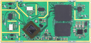
YELLOW beet P rev 1.1.
|
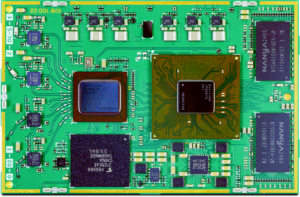
YELLOW beet H rev 1.1.
|
|
|---|---|---|---|
| Powerline chip | QCA7005 | QCA7005 | QCA7005 |
| Firmware version | Qualcomm HomePlug GreenPHY FW v3.0 | Qualcomm HomePlug GreenPHY FW v3.0 | Qualcomm HomePlug GreenPHY FW v3.0 |
| Configuration | EVSE (Electric vehicle charging stations) | PEV (Plug-in electric vehicles) | EN - 50561-1 |
| Host Interface | SPI | SPI | SPI |
| Mains Coupling | Yes, for ZC (zero - cross) only | No | Yes |
| Max data rate | 9.8 Mbps line data rate / 4.5 Mbps UDP data rate | 9.8 Mbps line data rate / 4.5 Mbps UDP data rate | 9.8 Mbps line data rate / 4.5 Mbps UDP data rate |
| Overvoltage protection | 4 kV | 4 kV | 4 kV |
| Max distance | According to ISO/IEC 15118-3 | According to ISO/IEC 15118-3 | 300 meters |
| Power Supply | 3.3V | 3.3V | 3.3V |
| Power Consumption | 1W (at 25º C) | 1W (at 25º C) | 1W (at 25º C) |
| Temperature Range | -40º C to +95º C (board temperature) | -40º C to +95º C (board temperature) | -40º C to +95º C (board temperature) |
| Size | 59 x 23 x 4 mm (up to 9 mm transformer height | 59 x 23 x 4 mm (up to 9 mm transformer height | 59 x 23 x 4 mm (up to 9 mm transformer height |
| Weight | 6.3 ±0.1 g | 5.8 ±0.1 g | 5.6 ±0.1 g |
| Mounting | Single Side | Single Side | Single Side |
| Certifications | CE | CE | CE |
| Applications | Electric vehicle charging stations | Electric vehicles | IoT, home control, appliances, smart plugs, industrilal automation, smart grid, electric meters, water heaters |